

The SDPG1000 Digital Pressure Gauge aligns well with wellhead pressure monitoring requirements because it is designed for high pressure fluid measurement while remaining self-contained and field deployable. In practical terms, it supports both routine verification checks and more investigative troubleshooting work where you need confidence in the displayed value and the ability to capture a maximum reading during a transient event.
Technically, the SDPG1000 combines an integrated pressure gauge design with a clear LCD for real time reading and peak value recording for capturing maximum pressure. This is useful in upstream work because pressure behaviour is often not perfectly smooth. Short spikes can occur during valve actuation, pump response, or system stabilisation. Having peak capture directly on the gauge helps turn a spot check into a more defensible measurement record.
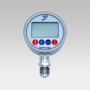
Key SDPG1000 capabilities
- Wide measuring range: 0 … 600 bar up to 0 … 2200 bar
- Accuracy options: 0.2 %FS or 0.5 %FS
- Battery powered: 2 × 1.5 V AA cells
- User friendly LCD display: clear real time readings
- Peak value recording: captures maximum pressure events
- Selectable units: kgf/cm², psi, MPa, bar
- Designed with resistance measurement via an isolation membrane, plus a low temperature drift amplifier and advanced A/D converter for consistent performance
Where it fits on a drilling site
At the wellhead and associated pressure points, a digital pressure gauge is commonly used as a local reference instrument to validate system behaviour during defined steps (pressurise, hold, depressurise) or to confirm expected pressures at specific points in time. Unlike permanently installed transmitters, a portable gauge is often used for verification, troubleshooting, or commissioning style checks, particularly where the goal is to validate what is actually happening at a point in the system with minimal setup.
In upstream drilling operations, it is also common that multiple stakeholders (site operations, service providers, engineering, and HSE) need to interpret the same results. That makes clarity of reading, unit consistency, and an ability to document a peak value especially helpful. The SDPG1000 selectable units and peak recording support that workflow without adding extra instrumentation complexity.
Common upstream scenarios where SDPG1000 is a strong fit:
- Pressure verification and spot checks at the wellhead
- Ramp and hold sequences where stability is assessed over a defined window
- Operational transitions (pump start/stop, valve changes) where short peaks may occur
- Field documentation support using observed values plus captured peak
Features and benefits for wellhead monitoring
When selecting a wellhead gauge, the practical outcome is usually tied to reducing uncertainty. This includes fewer ambiguous readings, fewer missed events, and less time spent repeating checks. Below are SDPG1000 features translated into upstream focused benefits.
Feature and benefit mapping:
- Up to 0…2200 bar range: supports high pressure wellhead contexts with adequate headroom and reduces range to limit measurement risk
- 0.2%FS / 0.5%FS accuracy options: align performance to the criticality of the check (tighter where needed, optimised where appropriate)
- Peak value recording: captures short duration spikes that may be missed during manual observation
- Selectable units (bar/psi/MPa/kgf/cm²): reduces conversion errors and improves consistency across teams and reports
- AA battery operation: practical for remote sites and quick deployments without relying on local power
- Isolation membrane, low drift amplification, and A/D conversion design: supports stable measurement behaviour for field use where conditions can vary
Modelled example: typical wellhead pressure behaviour
The modelled dataset below represents a simplified ramp, hold, and bleed pressure profile often used to emulate a pressure verification sequence. While real wells and surface systems can show more complex dynamics (including oscillations, thermal effects, and compliance in the system), this example demonstrates the two key behaviours you want to capture: steady state stability during a hold and transient response or peaks during transitions.
For an on-site workflow, the SDPG1000 supports the operator by providing continuous digital indication during the ramp and hold and recording the maximum pressure observed. Even when the displayed pressure appears stable, small excursions can occur and peak recording provides an additional data point that can be valuable in reporting.
Modelled dataset (bar)
Time (min) | Operation step | Pressure (bar) | Notes |
0 | Baseline | 3 | Stable baseline reading |
1 | Pump start | 35 | Initial pressurisation |
2 | Ramp | 90 | Controlled increase |
3 | Ramp | 150 | |
4 | Ramp | 210 | |
5 | Ramp | 260 | |
6 | Ramp | 300 | Approaching target |
7 | Ramp | 325 | |
8 | Target reached | 350 | Start hold window |
9 | Hold | 349 | Minor variation |
10 | Hold | 350 | Stable |
11 | Hold | 351 | Short transient (peak capture useful) |
12 | Hold | 349 | |
13 | Hold | 350 | |
14 | Hold | 348 | |
15 | Hold | 349 | End of hold window |
16 | Bleed down | 320 | Controlled depressurisation |
17 | Bleed down | 250 | |
18 | Bleed down | 150 | |
19 | Bleed down | 60 | |
20 | Return to baseline | 4 | Back near baseline |
How Stork Solutions can help
Delivering a robust wellhead pressure monitoring approach is not only about selecting a gauge. It is about ensuring the instrument specification matches the operational requirement and that field teams can apply it consistently. Stork Solutions supports customers by taking an outside in view of the application: what pressure range is truly required, what level of accuracy is appropriate, how readings will be documented, and what features (like peak capture and unit selection) will reduce on site friction.
For the SDPG1000 specifically, we can help you select the most suitable configuration in terms of range and accuracy, align the measurement approach with your internal procedures, and ensure you have a straightforward path to deploying reliable wellhead checks. If your application spans multiple well sites or teams, standardising on a practical gauge specification and workflow can materially improve consistency and reduce the time spent reconciling measurement differences between personnel and reports.
How we support your deployment:
- Range and accuracy selection: 0…600 bar through 0…2200 bar and 0.2%FS or 0.5%FS based on your operating envelope
- Application fit guidance: advice on how and where to use peak capture, unit standardisation, and documentation approach
- End to end instrumentation support: ensuring the overall solution matches the real operational requirement
Enquire here: SDPG1000 Digital Pressure Gauge
