

We define a pressure sensor as a device that converts applied force on a diaphragm into a measurable electrical signal. Our team of experts explain that pressure is force per unit area; when media deflect a diaphragm, strain changes resistance, capacitance or charge, which we condition and interpret. We provide practical clarity on how pressure sensors work, from piezoresistive bridges to capacitive plates and piezoelectric ceramics, so you can match principle to application. Our specialists design for media compatibility, temperature stability, and long-term drift, because accuracy starts with materials and structure. We can support you with insight into calibration, linearisation, and environmental compensation, ensuring repeatable performance in real installations.
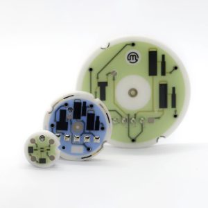
What Is a Pressure Sensor?
Pressure sensors are critical components that enable precise measurement of pressure in countless applications worldwide. That said, our pressure sensor definition is a device that converts applied gas or liquid pressure into an electrical signal for monitoring and control. In practice, it measures absolute, gauge, or differential pressure in bar, pascal, or psi, following performance definitions in IEC 61298-2:2020.
If your process needs reliable pressure measurement, the sensor translates mechanical stress into a measurable signal. Depending on the pressure measurement technology, that element might be a strain gauge sensor in a Wheatstone bridge, a crystal using the piezoelectric effect for dynamic events, a capacitive sensing diaphragm, or MEMS sensors. Outputs can include 4-20 mA, 0-10 V, and digital protocols like I2C or SPI. Sometimes the assembly with conditioning is called a pressure transducer, and a transmitter adds a scaled output signal for long cable runs.
From automotive engines to sterile bioreactors, common sensor applications span MAP and TPMS, hydraulics, HVAC, water networks, and aerospace test stands. At Stork Solutions, we match materials to media, selecting stainless steel, Hastelloy, or ceramic where compatibility matters. Plus, clean threads, correct torque, and a well-maintained snubber help improve stability in pulsating lines. According to EU Regulation 661/2009, tyre-pressure monitoring became mandatory for new passenger cars in 2014, driving adoption and rigorous sensor calibration techniques. So, how does the sensing element convert stress into a signal? Let’s move on to the physics that turn pressure into numbers.
Our engineers design around a diaphragm, isolation fill, electronics, and a sealed, welded housing so the process media never contacts the strain elements directly. Typical ranges run from a few millibar to 1,000 bar, specified in bar, psi, or Pa. We calibrate to UKAS ISO/IEC 17025:2017 traceability where required, documenting sensor output signal, linearity, and hysteresis. This underpins measurement repeatability.
How Do Pressure Sensors Work? The Basic Principle
At their core, pressure sensors transform physical pressure into measurable electrical signals using ingenious engineering. They rely on a flexible sensor diaphragm that deflects under force, converting that movement into a clean sensor output signal through piezoresistive, capacitive, or piezoelectric elements. At Stork Solutions, we design the pressure to electrical signal path, which is simple in principle.
Reliable measurement in harsh conditions needs a stable, long-term reference and a durable sensor diaphragm. Pressure, which is force per unit area, flexes the diaphragm when expressed in bar, kPa, or psi. In a strain gauge sensor, four resistors bonded to the diaphragm form a Wheatstone bridge; as resistance changes with strain, it produces a millivolt signal that’s amplified, filtered, and linearised. According to IEC 60770-1:2010, we evaluate performance across temperature and pressure ranges to characterise hysteresis, repeatability, and span.
Our engineers design around the pressure sensor working principle. The piezoelectric effect, discovered by Jacques and Pierre Curie in 1880, generates charge when a crystal is stressed, making it ideal for fast pressure transients. Capacitive sensing measures the change in capacitance between plates as the diaphragm moves, providing low power and high resolution at low pressures. MEMS sensors use silicon diaphragms on a chip, and media-wetted parts are often 316L stainless steel or Hastelloy to ensure compatibility with aggressive fluids.
So, how do you choose the right output signal? For control, 4–20 mA resists noise and cable runs, while 0–10 V is better for longer runs; digital I2C or SPI works well for modules. We calibrate zero and span with UKAS‑traceable standards, using sensor calibration techniques like thermal compensation across the range. According to BS EN 61326‑1:2021, electromagnetic immunity must be proven in various environments. In automotive intake systems, piezoresistive MEMS absolute pressure sensors report engine load (Bosch Automotive Handbook, 10th ed.). We also compare types and highlight where each pressure measurement technology excels.
Types of Pressure Sensors and How They Work
Pressure sensors come in various types, each leveraging unique technologies to measure pressure accurately. In practice, four families dominate: strain gauge, capacitive, piezoelectric, and MEMS. We’ll explain how each one converts applied pressure into an electrical signal, where they perform best, and what to keep in mind for installation, materials, and calibration.
| Type | Core mechanism | Typical uses | Strengths | Limitations | Output signal | Materials |
|---|---|---|---|---|---|---|
| Strain gauge sensor | Wheatstone bridge with metal‑foil or diffused resistors on a diaphragm; pressure induces strain, changing resistance | Industrial hydraulics, process transmitters, automotive oil pressure | Stable, wide ranges to very high pressure, mature pressure measurement technology | Temperature sensitivity, needs compensation and calibration | mV/V bridge, conditioned 4–20 mA, 0–10 V | Stainless steel diaphragm, adhesive‑bonded foil, nickel alloys |
| Capacitive pressure sensor | Capacitive sensing: a flexible diaphragm forms a capacitor with a fixed plate; pressure changes the gap and capacitance | Low differential pressure, HVAC filter monitoring, barometric reference, medical CPAP | High resolution at low pressures, low power | Susceptible to contamination, humidity, and mounting stress | Capacitance‑to‑digital, ratiometric voltage | Silicon, ceramic, glass substrates |
| Piezoelectric sensor | Piezoceramic or quartz generates charge under stress; a charge amplifier converts to voltage | Dynamic pressure: combustion, shock, vibration and NVH testing | Very fast response, usable above 100 kHz | Unsuitable for true static pressure due to charge leakage, needs conditioners | pC output, IEPE constant‑current voltage | Quartz or PZT crystals, high‑temperature housings |
| MEMS sensors | Micro‑machined silicon diaphragm with piezoresistors or capacitive elements, often with on‑chip ASIC | Automotive MAP and TPMS, smartphones altimetry, wearables | Small, low cost, integrated diagnostics | Packaging stress and media compatibility unless oil‑isolated | I²C/SPI digital, ratiometric voltage | Silicon die, gel or oil‑filled isolation, stainless or ceramic headers |
High‑pressure applications above 400 bar require careful material compatibility and installation torque control to avoid thread distortion. According to NPL guidance, piezoelectric devices excel in dynamic pressure but aren’t suited to static readings over time, while bridge‑based pressure transducers provide stable long‑term measurements. So, which type suits your application? Our engineers specify sensor output signals and calibration techniques to IEC 61298 and ISO/IEC 17025 practice, including deadweight testing and barometric references, and we align outputs to your control system—whether it’s 4–20 mA, 0–10 V, or digital. When done right, selection balances range, media, temperature, and expected drift across the service interval.
Pressure Sensor Components and Materials
The reliability of a pressure sensor hinges on the quality of its components and the materials chosen for construction. In 2025, core pressure sensor components include a diaphragm and sensing element, signal-conditioning electronics, a pressure port, seals, and a housing. Typical sensor materials are 316L stainless steel, silicon or ceramic elements, and alloys like Hastelloy or titanium, which are selected for media compatibility and sensor durability. At Stork Solutions, we specify materials to meet industry standards. For instance, we follow IEC 60770 for transmitters and ISO 15156 for sour-service resistance.
Stable, accurate industrial pressure measurement technology starts with the sensing element. A strain gauge sensor uses a silicon Wheatstone bridge on a diaphragm to create a millivolt output; then an ASIC amplifies, linearizes, and compensates it to 4 to 20 mA, 0 to 10 V, or digital I2C/SPI. For dynamic events, the piezoelectric effect in quartz generates charge, while capacitive sensing with a ceramic diaphragm offers excellent long-term low-pressure stability and repeatability. Our engineers carefully specify oil fill viscosity, port geometry, and EMI shielding to strike a balance between response time and noise immunity. Many pressure transducer designs use oil-filled stainless isolating diaphragms to protect MEMS sensors from corrosive media, vibration, and thermal shock in automotive manifolds and hydraulic blocks.
So, how do you choose sensor materials for your media? Corrosive seawater points to titanium or Hastelloy; chlorides can damage 304, so 316L or duplex is a safer bet. Sour hydrocarbon streams require alloys qualified to NACE MR0175/ISO 15156:2020, and oxygen service mandates oil-free cells with ceramic or stainless diaphragms and fluorinated fill. Seals matter: FKM works well for oils, EPDM for water-based fluids, and PTFE or FFKM for solvents, with hygienic grades that meet FDA 21 CFR. Housing and cable glands are specified to IEC 60529 for IP ratings, while calibration techniques need to consider the thermal behavior of silicon versus ceramic to maintain accuracy over time.
Manufacturing Process of Pressure Sensors at Stork Solutions
Our state-of-the-art manufacturing process combines advanced design and rigorous testing to deliver superior pressure sensors. We manufacture in-house, with in-house design and engineering, moving from 3D CAD design and rapid prototyping to precision assembly, automated calibration, and verification, with sensor quality control embedded so each pressure transducer meets its specified range, output, and environmental rating.
Once you’ve defined your application and medium, our engineering team will match the right sensing principle and materials. Our pressure sensor manufacturing workflow below follows ISO 9001:2015 and IEC 61326-1 EMC.
- Requirements capture and concept: confirm constraints, pressure ranges from mbar to 1000 bar, output signal, and media; choose strain gauge sensor, piezoelectric effect, capacitive sensing, or MEMS sensors.
- 3D CAD design and simulation: create models, run FEA on 316L or Hastelloy diaphragms, and design wetted paths to minimise hysteresis and creep.
- Rapid prototyping: print housings and jigs, test fits, while sensing elements are laser-trimmed or bonded on pilot builds for quick iteration.
- Precision machining and clean assembly: CNC-machine ports and bodies, clean to ISO 14644, then weld, oil fill, and seal to protect the measurement cell.
- Calibration, compensation, and characterisation: automated benches apply multi-point pressure and temperature profiles; coefficients go to EEPROM; techniques follow ISO/IEC 17025 traceability.
- Verification and compliance testing: we verify IP per IEC 60529, shock and vibration to IEC 60068, EMC to IEC 61326-1, and run burst, leak, and cycle tests.
- Final configuration and serialisation: set output to 4 to 20 mA, 0 to 10 V, or I2C, SPI, or CAN; record full traceability.
How do you select the right output signal? Building on this, we map it to noise immunity, cable length, and update rate, then document the choice. This same attention to detail in pressure measurement technology extends to UKCA and CE conformity and documentation in 2025, RoHS and REACH materials review, and pack-out, supporting automotive, HVAC, and process installations.
Pressure Sensor Calibration and Accuracy
Accurate pressure measurement depends on precise calibration and clear limits. At Stork Solutions, we calibrate sensors against traceable standards, using deadweight testers or pressure controllers within an ISO/IEC 17025 framework at controlled temperature and humidity, then we adjust zero and span. Sensor accuracy typically ranges from ±0.05% to ±1% of full scale, depending on the technology, range, and installation.
For high-accuracy pressure sensor calibration, we start with primary methods and then use standards for routine ranges. Deadweight testers set reference points, while pressure controllers step sensors through the span. We apply ISO/IEC 17025 calibration standards and IEC 61298-2 reference conditions. Up-, down-, and return-to-zero checks across 5 to 11 points help us quantify linearity, hysteresis, and repeatability, and then we adjust zero and span on the pressure transducer if allowed. These sensor calibration techniques really are the backbone of pressure measurement technology in industry.
So, what actually degrades sensor accuracy in service? Temperature shifts drive bridge resistance changes in a strain gauge sensor, bias piezoelectric effect readings, and alter plate spacing in capacitive sensing, especially in MEMS sensors. Installation matters too. Mounting orientation, vibration, overpressure, media compatibility, and electrical noise on the sensor output signal all contribute to errors. IEC 61298-2 sets reference conditions, so any departures must be stated on certificates. We mitigate these influences with thermal compensation, mechanical isolation, and noise filtering in design and during commissioning.
Pressure Sensor Applications Across Industries
From automotive to healthcare, pressure sensors play a role in safety and efficiency. It’s worth noting that they’re used across various sensor industries, including automotive, oil and gas production, HVAC and building services, medical, water treatment, and food processing, wherever pressure measurement technology drives control or protection. At Stork Solutions, we supply into ISO 26262:2018, ATEX 2014/34/EU, and IEC 60601 environments.
- Automotive: MAP/boost control, fuel rail pressure, brake hydraulics, and tyre pressure monitoring. MEMS sensors and strain gauge sensor elements feed ECUs via analog, SENT, or CAN. Since 2014, TPMS has been mandatory in EU cars (Regulation (EC) No 661/2009). The benefits include emissions control and reliability.
- Oil and gas: wellhead, pipeline, and separator monitoring using industrial pressure sensors with ATEX/IECEx. API 6A (2018) recognises equipment ratings up to 103.5 MPa. We specify 316L or Hastelloy wetted parts, snubbers, and remote seals to resist sour service. As a result, there are fewer trips and leaks.
- HVAC and building services: chiller and boiler protection, filter differential pressure, and VAV airflow. Common sensor output signal choices are 4-20 mA or 0-10 V into BMS. EN 378:2016 guides refrigerant safety. Gains include energy efficiency and stable comfort.
- Medical: ventilators, infusion pumps, and non-invasive blood pressure devices. The piezoelectric effect and capacitive sensing appear in flow and pressure modules, alongside precise pressure transducer designs. Standards include IEC 60601-1 and ISO 80601-2-30:2018. The key consideration is the benefits of patient safety and traceable calibration.
Across pressure sensor applications, success really depends on matching the type to the duty. That means selecting strain gauge, piezoelectric, or capacitive architectures, defining pressure ranges and units, and choosing a sensor output signal that your controller expects. Our engineers specify material compatibility, thread forms, and snubbers, then set installation practices to avoid vibration and ingress. We align sensor calibration techniques with ISO/IEC 17025:2017, ensuring results are traceable. These choices link applications back to working principles and the pressure transducer versus transmitter decision.
Pressure Sensors vs Pressure Transducers and Transmitters
Understanding the distinctions between sensors, transducers, and transmitters is key to selecting the right device. A pressure sensor is the primary element that changes resistance, capacitance, or charge with applied pressure. A transducer adds basic conditioning to present a stable voltage. A transmitter linearises, compensates, and outputs 4-20 mA or HART-ready signals that plants expect in 2025.
| Device | Core function | Sensor output types | Typical uses | Technologies |
|---|---|---|---|---|
| Pressure sensor | Primary sensing element only | mV/V bridge, capacitance change, charge | Embedded designs with custom conditioning | Strain gauge, capacitive, piezoelectric, MEMS |
| Pressure transducer | Amplifies and linearises to a voltage | 0.5 to 4.5 V, 1 to 5 V | Short cable runs to ECUs or PCBs | Piezoresistive MEMS, strain gauge |
| Pressure transmitter | Full conditioning, compensation, isolation | 4-20 mA, HART, RS-485/Modbus | Long runs to PLC/DCS, harsh environments | Piezoresistive or capacitive MEMS |
Stable, accurate measurement over distance favours current-loop transmitters. In pressure measurement technology, current signals resist noise and voltage drop across hundreds of metres, and NAMUR NE43 specifies fail-safe limits at 3.6 mA and 21 mA for diagnostics. For plants and HVAC, 4-20 mA with HART remains the go-to choice into 2025.
Your application needs may point the other way. In automotive intake manifold sensing, you’ll typically find 0.5 to 4.5 V ratiometric outputs into an ECU, with SAE J2716 SENT or CAN on newer platforms. It’s worth noting that we at Stork Solutions specify transducers here to minimise latency, while a bare sensor suits teams designing their own conditioning ASIC.
Our engineers calibrate devices via multi-point pressure and temperature mapping, then apply polynomial correction; ISO/IEC 17025 accredited labs verify traceability. So, which device suits a short-run PCB versus a long cable into a PLC? Use a sensor or transducer for the PCB, and a transmitter for the PLC.
In short, the decision between a pressure sensor and a transducer really depends on distance, noise, EMC, and calibration.
Conclusion
At Stork Solutions summarise the essentials: pressure sensors translate force on a diaphragm into an electrical output via reliable transduction. Our team of experts see the core principle as balancing mechanical strain with signal stability to represent absolute, gauge or differential references. We provide clarity on common mechanisms, including piezoresistive strain gauges, capacitive plates, and piezoelectric crystals for dynamic events. Our specialists emphasise that selection hinges on pressure range, media compatibility, temperature behaviour, accuracy class and environmental protection. We can support you in specifying, integrating and calibrating sensors for PLCs, data acquisition, or safety loops across industrial and laboratory contexts.
