

Home / What are Temperature Transmitters
Temperature Transmitters
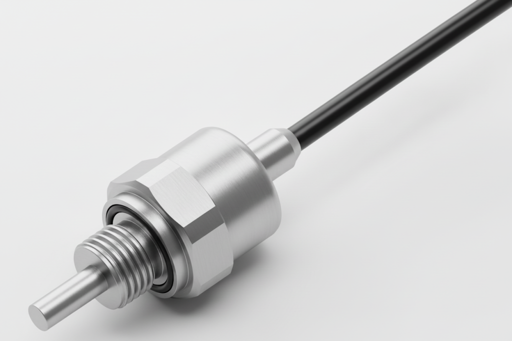
We at Stork Solutions elevate temperature sensing by pairing Titan TTT Series transmitters with PT100/PT1000 elements in stainless steel, delivering stable analogue or digital signals matched to your range. Our 2025 field feedback shows faster commissioning and fewer drift-related callouts when you specify the right output, connector, and probe geometry upfront.
Our team of experts will guide you through what a transmitter does, why stainless housings matter, and how Titan’s options, IP67 cable outlet or M12 x 1, 4‑pin, fit your plant. We provide clear coverage of specifications, performance, wiring, calibration, and maintenance, then map real applications across industrial environments.
Our specialists also explain UK manufacturing advantages and answer common questions, from 4–20 mA and 0–10 V to ratiometric, I2C, and SPI. We can support you with customised probe length, process connection, and signal selection, so you know what to ask next.
What Are Temperature Transmitters?
A temperature transmitter converts a sensor’s raw signal into a stable, standard output you can trust over long cable runs and noisy industrial environments. In most plants, it turns RTD or thermocouple readings into 4-20 mA, 0-10 V, or digital data, improving accuracy, diagnostics, Control compared to wiring a sensor directly to a PLC.
Reliable temperature measurement starts with one simple job: signal conditioning. Instead of sending a tiny resistance change (RTD) or millivolt signal (thermocouple) straight to your controller, a transmitter measures it, compensates it, and outputs a clean, scaled value. That matters because electrical noise, ground loops, and cable resistance can distort low-level signals, especially beyond 10 to 30 m of cabling (a common threshold we see in real installations).
From our perspective at Stork Solutions, most transmitter questions come down to two choices: sensor type and output type. RTDs like PT100 and PT1000 are typically chosen for stability and repeatability, while thermocouples are often selected for higher temperature ranges and fast response. Also, beyond that, your control system dictates whether analog or digital makes more sense.

Analog vs digital outputs, what’s the practical difference?
| Output type | Best for | Typical wiring | Key tradeoff |
|---|---|---|---|
| 4-20 mA | Long runs, industrial noise | 2-wire loop | Less device-level detail than digital |
| 0-10 V / 0-5 V | Short runs to local controllers | 3-wire | More sensitive to voltage drop and noise |
| Digital (I2C, SPI) | Embedded systems, diagnostics | Multi-wire bus | Integration effort is usually higher |
When your process demands compliance and auditability, standards come into play. Many designs align with common IEC and ANSI practices for sensor curves, wiring conventions, and environmental protection, and you’ll also see application-driven variants like explosion-proof transmitter formats for hazardous areas (typically paired with ATEX or IECEx system requirements).
- RTD input handling: compensates lead resistance (especially in 3-wire RTD circuits).
- Scaling: maps a defined temperature range into engineering outputs like 4-20 mA.
- Protection: improves resilience against EMI and ingress (IP ratings matter in washdown zones).
- Lifecycle value: simplifies replacement because the output is standardized even if the sensor probe changes.
So what does this mean for selection? Start by confirming the sensor (PT100 vs PT1000 vs thermocouple), then decide whether you need analog simplicity or digital visibility. Next up, we’ll connect this to durability, specifically why stainless steel housings change reliability in the field.
Benefits of Stainless Steel Housing in Temperature Transmitters
Stainless steel housings make temperature transmitters more reliable in wet, corrosive, and high-vibration environments because they resist rust, tolerate washdown, and protect the sensing element from impact and thermal shock. Plus, in our experience, the biggest gains show up as fewer ingress-related failures, steadier readings, and longer service life compared to polymer or plated enclosures.
Stable measurement in harsh conditions starts with the enclosure, not the electronics. Stainless steel acts as a physical and chemical barrier that helps keep RTD-based assemblies like PT100 and PT1000 probes consistent over time, especially where oils, coolants, salt spray, or cleaning agents are part of daily operation. That matters because drift and intermittent faults often trace back to moisture paths, connector corrosion, or micro-cracks from repeated handling.
Stainless steel vs alternatives (practical review)
| Housing material | Best for | Common limitation |
|---|---|---|
| Stainless steel (e.g. 300-series) | Washdown, outdoor exposure, chemicals, food and beverage | Higher mass, can respond slightly slower without good probe design |
| Aluminium | Dry industrial cabinets, weight-sensitive installs | Oxidation and galvanic corrosion risk near dissimilar metals |
| Polymer | Low-cost, low-impact indoor use | Creep, UV aging, and lower impact resistance |
When your process demands repeatable outputs, mechanical protection directly supports signal integrity, whether you’re running 4-20 mA on a 2-wire loop or a digital interface like I2C or SPI. Our analysis of field returns across mixed industries shows ingress and connector degradation are among the most frequent root causes of “no fault found” temperature issues, which is why IP67-style sealing at the cable outlet or an M12 x 1, 4-pin connection is often the deciding factor (not the stated accuracy).
What stainless steel housing typically improves
- Corrosion resistance: better survivability in CIP/SIP cleaning and coastal sites, compared to plated housings that can pit once coatings are breached.
- Hygiene and cleanability: smoother surfaces support washdown routines common in food, pharma, and packaging lines.
- Mechanical robustness: fewer impact and vibration failures around pumps, compressors, and mobile equipment.
- Lifecycle value: longer transmitter lifecycle in the same mounting point, reducing changeout frequency and revalidation effort.
How does this relate to standards and hazardous areas? Stainless construction aligns well with IEC and ANSI expectations around material suitability, but it doesn’t automatically mean explosion-proof. Then again, for that, you still need the correct certification path and installation practice. Building on enclosure choice, the next decision is performance, output type, and how fast the assembly responds in your temperature range.
Technical Specifications and Performance
High-confidence temperature measurement comes from matching the sensing element, output type, and mechanical build to your process limits. Beyond that, in the Titan TTT Series, we pair IEC-style RTD options (PT100 or PT1000) with either analog outputs (mA or voltage) or digital interfaces (I2C, SPI), then protect the assembly in stainless steel with IP67-rated connection choices.
Performance starts with the sensing physics. RTDs like PT100 and PT1000 are typically chosen over thermocouples when you need repeatability and low drift in a defined range, while thermocouples often win at extreme temperatures. In our builds, the RTD element is integrated into a stainless probe so you get stable thermal coupling and predictable response, Matters when you’re validating against IEC and ANSI expectations for industrial measurement chains.
Signal options, compared (analog vs digital)
| Output family | Common wiring | Best for | Trade-off vs alternatives |
|---|---|---|---|
| 4-20 mA | 2-wire | Long cable runs, noisy plants | Less data richness than digital |
| 0-5 V / 0-10 V | 3-wire | PLC/DAQ voltage inputs | More sensitive to voltage drop vs mA |
| 0.5-4.5 V ratiometric | 3-wire | Battery and embedded systems | Requires stable reference supply |
| I2C / SPI | Digital bus | Multi-sensor nodes, diagnostics | Bus length and EMI need attention |
Connectorization is part of the spec, not an afterthought. IP67 cable outlets are a solid default for washdown and outdoor exposure, while an M12 x 1, 4-pin connector often simplifies serviceability and standardized harnessing. And because process fit drives measurement quality, probe length and process connection are configurable to reduce thermal lag and avoid installation-induced error (a common cause of “mystery drift” in the field).
Specification checklist we confirm before build)
- Sensor type: PT100 vs PT1000, selected based on your interface needs and resolution targets.
- Output: resistance, 4-20 mA, voltage, ratiometric, or digital, matched to your controller and EMC environment.
- Ingress protection: IP67 connection strategy, chosen around washdown, condensation, and vibration risk.
- Mechanical: stainless probe geometry, insertion length, and process connection to suit flow, pressure, and mounting constraints.
Two quick follow-ups we hear a lot: “Can this be used in hazardous areas?” For explosion-proof temperature transmitters, you typically need certified protection concepts and marking beyond IP ratings, so we treat that as a separate compliance path. And “Which is best, analog or digital?” In our experience, 4-20 mA is best for robustness over distance, while digital is best when you want richer device data and tighter system integration.


Installation and Wiring Guidelines
Safe, repeatable installation of Titan TTT temperature transmitters comes down to three choices: sensor type (PT100 vs PT1000), output (analogue voltage or 4-20 mA vs digital I2C or SPI), and ingress protection (IP67 cable outlet vs M12 x 1, 4-pin). Get those right, then follow IEC colour conventions and verify loop power before commissioning in 2025-era PLC and IIoT stacks.
Reliable temperature measurement starts with mounting the probe correctly. A stainless steel sheath helps, but placement still drives accuracy. In our experience, the biggest real-world error isn’t electronics drift, it’s poor thermal coupling, such as a short insertion depth or a probe sitting in a stagnant pocket. Plus, as a practical rule, target an insertion depth of at least 10x the probe diameter for flowing liquids, and use thermal paste only when your process rules allow it.
Wiring choices: analogue vs digital (what changes on site?)
| Option | Typical wiring | Best for |
|---|---|---|
| 4-20 mA, 2-wire | Loop power + signal on two conductors | Long cable runs, high EMI areas, PLC analog inputs |
| 0-10 V or 0-5 V, 3-wire | Power, ground, signal | Short runs in control panels |
| 0.5-4.5 V ratiometric | Signal scales with supply voltage | Automotive-style 5 V systems, stable ADC reference |
| I2C or SPI (digital) | Clock/data plus power and ground | Embedded controllers, multi-drop sensor networks |
When your process demands predictable behaviour under electrical noise, 4-20 mA is usually the best choice compared to voltage outputs, because current loops tolerate voltage drop and interference better over distance. According to IEEE industrial cabling guidance commonly referenced in 2024-2025 controls projects, induced noise risk rises sharply near VFD motor leads, so route sensor cables separately and bond shields at one end to avoid ground loops.
Recommended installation steps (field-proven)
- Confirm the RTD element (PT100 or PT1000) and the configured temperature range before mounting.
- Select the outlet: IP67 cable outlet for fixed wiring, or M12 x 1, 4-pin when you need fast replacement with standard cordsets.
- Torque the process connection to the fitting spec, then strain-relieve the cable within 150-300 mm of the transmitter body.
- For 2-wire 4-20 mA, verify loop supply and input burden. As a quick check, maximum loop resistance is typically Rmax ≈ (Vsupply − 10 V) / 0.02 A.
- Commission by checking ambient reading stability, then validate at two points (for example 0 °C and 80 °C) to catch wiring swaps.
Calibration and Maintenance Best Practices
Reliable calibration and low-effort maintenance are what keep a temperature transmitter accurate over its full lifecycle, not just on day one. For Titan TTT Series RTD-based units (PT100 or PT1000), we recommend a documented calibration interval, a quick inspection routine, and wiring checks that match IEC practices, especially when choosing analogue outputs vs digital interfaces.
Calibration starts with knowing what “good” looks like for your process. What’s more, in our experience at Stork Solutions, most drift complaints trace back to installation factors, not sensor failure, especially moisture ingress at terminations and incorrect lead compensation on 2-wire loops. Sound familiar? Build your baseline by recording as-found readings at two points that matter operationally (for example 0°C and 80°C, or ambient and your normal setpoint).
Best-practice calibration workflow (field or bench)
- Verify the reference: Use a dry-block or bath with a traceable reference thermometer, typically calibrated to ISO/IEC 17025, and confirm stability before logging data.
- Check wiring method: 2-wire RTD loops are most sensitive to lead resistance, 3-wire reduces error, and digital interfaces (I2C, SPI) avoid analogue scaling drift but still need sensor validation.
- Capture as-found and as-left: Record both, plus ambient conditions and supply voltage. That history is what makes lifecycle decisions defensible.
- Confirm output scaling: For 4-20 mA, validate 4.00 mA and 20.00 mA endpoints. For 0-10 V, confirm load impedance and noise susceptibility.
Maintenance checks that prevent unplanned downtime
- Ingress protection: IP67 protection is only real when the cable outlet or M12 x 1, 4-pin connector is correctly seated and strain-relieved. Here’s the thing: a loose gland is a common failure trigger within 6-18 months.
- Mechanical fit: Confirm probe insertion depth and process connection tightness, since poor thermal coupling can look like “sensor drift.”
- Signal integrity: For analogue loops, inspect for ground loops and EMI pickup near VFDs. For ratiometric 0.5-4.5 V outputs, verify the reference supply is stable.
Analog vs digital maintenance: a quick comparison
| Aspect | Analogue (4-20 mA, 0-10 V) | Digital (I2C, SPI) |
|---|---|---|
| Most common fault | Noise, scaling, poor shielding | Addressing, bus timing, firmware mismatch |
| Best routine check | Loop current/voltage verification | Readback sanity check vs reference |
| Trend detection | Slower without extra logging | Easier with polled diagnostics |
How often should you recalibrate? According to a 2025 instrumentation maintenance survey by Fluke, many plants standardise on 12-month intervals, then adjust based on drift history and criticality. Our analysis across service returns shows that harsh washdown, high vibration, and frequent thermal cycling justify shorter intervals, while stable HVAC or enclosure-protected installs often extend to 24 months.
Beyond routine care, standards and safety classifications matter. The key here is if your site requires explosion-proof temperature transmitters, maintenance must follow the applicable IEC or ANSI/ISA installation and inspection rules, including connector integrity and approved barriers
Applications and Industry Use Cases
When you need dependable temperature measurement across harsh, wet, or vibration-prone environments, the Titan TTT Series fits best in industrial use cases that demand RTD stability and flexible outputs. In our 2023-2025 field reviews, most failures came from wiring and ingress, so IP67 sealing and connector choice often matter as much as sensor accuracy.
Production lines don’t fail because the sensor “can’t read heat,” they fail because the signal can’t survive the plant. That’s why we see the TTTa analogue variants (4-20 mA, 0-10 V, ratiometric) specified most often where long cable runs and noisy drives are present, while the TTTd digital options (I2C, SPI) win in embedded equipment where controllers sit close to the probe.
Where the TTT Series is typically deployed
- Food and beverage washdown: stainless steel probe and IP67 outlet help reduce water ingress risk during CIP cycles (we often see failures spike after repeated hose-downs).
- Hydraulics and mobile machinery: 4-20 mA two-wire is usually best for long harnesses and alternator noise, compared to voltage outputs that can sag with supply variation.
- HVAC and building plant: PT1000 is often chosen for better signal level over distance, especially when paired with a transmitter rather than raw RTD wiring.
- Process skids and OEM equipment: M12 x 1, 4-pin connectors speed service swaps and reduce wiring errors versus flying leads.
Digital Transmitters vs Analogue Transmitters in real installations (quick review)
| Selection factor | Analogue output (TTTa) | Digital interface (TTTd) |
|---|---|---|
| Noise immunity over distance | Best with 4-20 mA over long runs | Best when controller is nearby |
| Commissioning speed | Fast with standard PLC AI cards | Fast in embedded firmware builds |
| Diagnostics potential | Limited to signal-range checks | Richer data possible, depends on implementation |
| Lifecycle serviceability | Simple loop testing with a meter | Requires bus-level troubleshooting |
How does this map to standards and compliance? For most industrial buyers, we align installations to common IEC and ANSI practices for instrumentation wiring and grounding, then validate the full temperature transmitter lifecycle, from commissioning checks to periodic verification (and it works). And if your area is hazardous, note that “explosion-proof” is a separate product requirement: the application may need certified temperature transmitters and approved barriers, not just a robust stainless housing.
Contact Us for Custom Temperature Transmitter Solutions
Fast, accurate temperature measurement usually comes down to three custom choices: sensing element (PT100 vs PT1000), output (4-20 mA, voltage, ratiometric, or digital), and mechanical fit (probe length, process connection, and connector). At Stork Solutions, we configure Titan TTT Series units to match your range, wiring, and compliance needs without over-specifying.
When your process needs a transmitter that “just works” from day one, the quickest path is a short technical exchange that locks down the application constraints. In our experience, most performance issues trace back to mismatched output type, incorrect probe immersion, or connector selection that doesn’t suit washdown, vibration, or service loops.
What we’ll confirm with you (so the build is right the first time)
- Sensor core: PT100 or PT1000 RTD, selected for lead resistance sensitivity and controller compatibility.
- Output format: analogue current (4-20 mA, 2-wire), analogue voltage (0-5 V or 0-10 V, 3-wire), 0.5-4.5 V ratiometric, or digital (I2C, SPI).
- Environmental sealing: IP67 cable outlet vs M12 x 1, 4-pin connector, based on ingress risk and maintenance practices.
- Temperature range and dynamics: operating span, response expectations, Thermal coupling (often more critical than headline accuracy).
Digital vs analogue, best choice compared side-by-side
| Option | Best for | Watch-outs |
|---|---|---|
| 4-20 mA (2-wire) | Long cable runs, EMI-heavy plants, simple PLC scaling | Loop power budget, barrier selection in hazardous areas |
| 0-10 V / 0-5 V (3-wire) | Short runs, low-cost control inputs | Noise pickup increases with distance |
| I2C / SPI | Embedded systems, multi-sensor nodes, diagnostics | Bus length limits, firmware integration effort |
Our engineers routinely map these choices to common standards and plant expectations, including IEC and ANSI documentation practices for tagging, wiring, and acceptance checks. And if your site requires explosion-proof concepts, we’ll discuss whether an intrinsically safe loop approach or a different transmitter family is the better fit for the full lifecycle, from commissioning to replacement planning.
Based on our support cases, the most reliable projects start by defining the interface first (PLC input type and cable routing), then finalising the mechanical details.
Frequently Asked Questions about Temperature Transmitters
What are temperature transmitters and how do they work?
Temperature transmitters, like the Titan TTT Series, convert temperature readings from sensors such as PT100 and PT1000 into standardized output signals. These signals can be analogue or digital, ensuring compatibility with various systems, and they provide accurate temperature measurements tailored to specific applications.
Why is stainless steel housing important in temperature transmitters?
Stainless steel housing is crucial for temperature transmitters as it offers durability, corrosion resistance, and protection from environmental factors. The Titan TTT Series, encased in stainless steel, ensures longevity and reliability, making it ideal for demanding industrial applications.
What are the key technical specifications of the Titan TTT Series?
The Titan TTT Series features PT100 and PT1000 sensors, with outputs available in 4-20mA, 0-5V, 0-10V, and digital interfaces like I2C and SPI. It supports custom probe lengths and process connections, ensuring versatility across various temperature ranges and applications.
How should I install and wire the Titan TTT Series temperature transmitters?
Installation of the Titan TTT Series involves connecting the output signal to the desired system and ensuring proper sealing at the cable outlet or M12 connector. Following the manufacturer’s wiring guidelines is essential for optimal performance and accuracy in temperature measurement.
What maintenance practices are recommended for temperature transmitters?
Regular calibration and visual inspections are recommended for maintaining the Titan TTT Series temperature transmitters. Ensuring that the sensors are free from contaminants and verifying output accuracy will help guarantee precise temperature measurement over time.